The extra-convenient places to plug things in on the front of your case won’t work unless you hook them up correctly inside your PC.
Specific Ports in a Storm
We hooked up the switches and audio in the previous article. Though we will now be able to turn the computer on and off, we still can’t use all those connectors on the front of our case. Let’s hook those up.
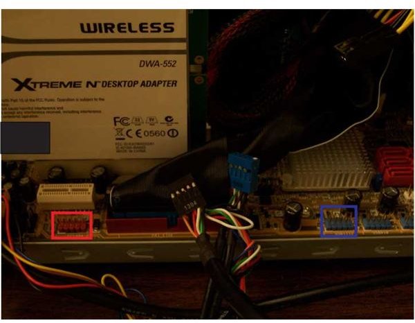
The picture shows something we have to watch for: USB and Firewire connectors are physically identical. Mind you, hooking them up to the wrong connectors on your motherboard can cause significant damage when the power is switched on. Almost all Firewire connections have some kind of red colour coding. Failing that, there is the writing on the mobo itself, and the writing about the mobo (its manual). Note that Firewire is often referred to by its engineering code: IE 1394 or IEEE 1394.
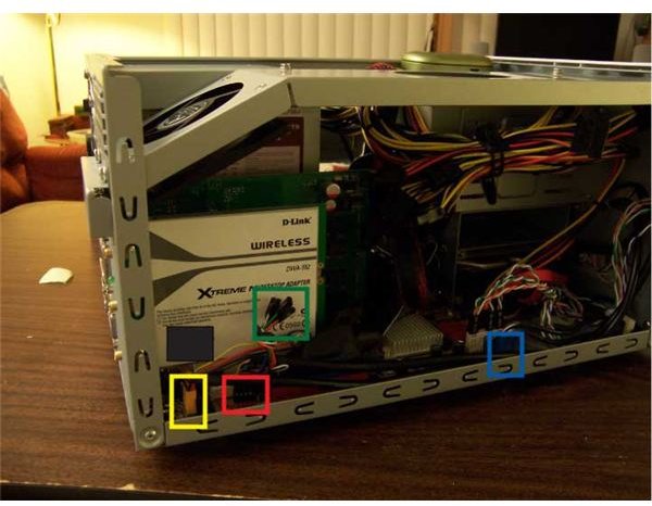
Depending on the age of your hardware, USB and Firewire connections may have to be made individually, meaning one pin at a time. The picture shows the extra (unused) wires on our Firewire connector in a green rectangle, for instance. Though things are currently pretty standardized, an older motherboard may have different pin assignments. Again, check your manual if in doubt. The picture also shows the Audio connectors from the previous article in yellow, as well as the USB and Firewire connectors in blue and red respectively. The front panel lights and switches, again covered in the previous article, are connected just behind the USB cables.
If your motherboard uses the more convenient block connectors, orient them by matching the blocked hole and missing pin. And just so you don’t panic and think something is missing: One USB connection on the motherboard can support two USB ports; so you can stop looking for the missing cable.
If your case has eSATA (ours does not), hook up the data cable to one of the SATA ports on the motherboard. You also have to connect a cable to the Power Supply. This is largely identical to how we connected the internal SATA drive itself in the this article .
Keeping Things Neat
The second picture above shows how we ran two cables (Audio and Firewire) to the rear along the bottom corner of the case. The switch, light, fan, and USB cables only had to reach the near corner of the motherboard. We tied the smaller wires together and tucked them, along with the USB cable, back up into the front panel as much as possible. The remaining slack was bundled and tucked into the lower corner.
If you think this is the kind of tidying up we do when we are just about done, you’re right! In our next article, we close up our new home-built PC and flick the switch.
This post is part of the series: Building a PC
We show you how to build PC, step by step, with pictures.
- Building a PC: Open Your Case and Get to Work!
- Building a PC: Time to Install the Motherboard
- Building a PC: Installing a Core 2 CPU
- Building a PC: How to Install a Power Supply Unit
- Building a PC: Installing Memory
- Building a PC: Installing an Optical Device
- Building a PC: Installing a Hard Drive
- Building a PC: Installing Graphics and Other Expansion Cards
- Building a PC: Installing Fans
- Building a PC: Power Connections for the Motherboard and Fans
- Building a PC: Connecting the Hard Disk and Burner
- Building a PC: Connecting the Case’s Switches and Audio
- Building a PC: Connecting the Case’s Front Panel Ports – USB, Firewire, and eSATA
- Building a PC: Closing the Case
- Building a PC: Connecting Peripherals