In this article we continue our look at various types of networks by digging into the working of routed packet delivery.
Routed Networks
Another way to segment a network is with a router. The primary purpose of a router is to connect two or more network segments, while routing incoming packets to the appropriate segment. In addition to routing, routers differ from switches by not allowing broadcasts to pass from one segment to another. This feature further reduces unwanted traffic passing by each NIC.
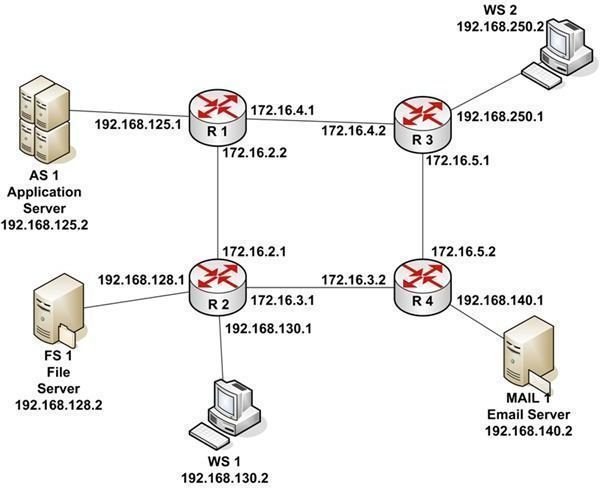
Routing is the movement of IP Datagrams from one network segment to another. Routers make this happen by learning the network to which they’re attached so that they route each datagram to the appropriate next hop. Let’s take a look at an example depicted in Figure 1.
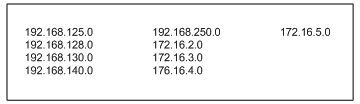
There are four routers: R1, R2, R3, and R4. There are also three servers and two workstations. The entire network uses a subnet mask of 255.255.255.0. So the first three octets of each IP address is the network segment address. The routers separate the network into nine network segments, or subnets, as listed in Table 1.
Note that the connections between routers are actually subnets with their own network addresses. Each router interface is assigned an IP address.
If WS 1 wants to send a packet to MAIL 1, it creates an IP Datagram with a Destination IP Address of 192.168.140.2 and a Source IP Address of 192.168.130.2. Using the subnet mask, WS 1 calculates that the destination subnet is 192.168.140.0. Comparing this address to its own subnet address of 192.168.130.0, WS 1 knows that MAIL 1 is on a different subnet. WS 1 also knows that to get to a device on another subnet, it must use its default gateway. A default gateway is the address of a router port on a workstation’s own subnet that the network engineer configures when setting up the workstation’s TCP/IP configuration. If a workstation is not configured with a default gateway, it can only communicate with devices on its own subnet. In this case, WS 1 is configured with the default gateway address of 192.168.130.1.
As we’ve seen in previous examples, one network device can’t communicate with another network device unless it knows its MAC address. WS 1 looks in its ARP cache to see if it has the MAC address associated with 192.168.130.1. Since it hasn’t recently communicated with that IP address, it doesn’t have the proper MAC address. So WS 1 sends a broadcast packet onto its subnet asking the device with IP address of 192.168.130.1 to return its MAC address. R2 responds with the MAC address of its port with that IP address. WS 1 constructs an Ethernet packet with the MAC address of its default gateway as the Destination Address and its own MAC address as the source address. It then sends the packet to R2.
When R2 receives the packet, it extracts the IP Datagram and applies the subnet mask to the Destination IP Address. Since routers in a network communicate information to other routers on the network about attached subnets, R2 knows that to get to subnet 192.168.140.0 it should route the packet to R4 address 172.16.3.2. R2 looks in its memory to see if it has the MAC address associated with that IP address. Since it has recently communicated with that port, it has the proper MAC address. If the MAC address hadn’t been in memory, R2 would have placed a broadcast MAC address request on subnet 172.16.3.0.
R2 reconstructs an Ethernet packet, containing the IP Datagram from WS 1, with the Destination MAC Address of port 172.16.3.2 on R4 and a Source MAC Address for the R2 port with an IP address of 172.16.3.1. R2 places the packet on subnet 173.16.3.0. When R4 receives the packet, it extracts the IP Datagram. Once again, the subnet mask is applied to the Destination IP Address. This time, R4 knows that subnet 192.168.140.0 is connected to one of its ports.
Checking its ARP cache, R4 locates the MAC address for 192.168.140.2. It reconstructs an Ethernet packet with a Destination MAC Address for MAIL 1 and a Source MAC Address containing the MAC address of router port 192.168.140.1. R4 places the packet on subnet 192.168.140.0. MAIL 1 receives the packet, extracts the IP Datagram and the transmitted data. Remember that the Destination IP Address and the Source IP Address have not changed as the IP Datagram was routed across the network. Because of this, MAIL 1 knows where to send a return packet.
There is one more important thing to know about routed networks. If designed properly, information can be routed around failing subnets. For example, if subnet 172.16.3.0 had been unavailable, the IP Datagram from WS 1 would have been routed to subnet 172.16.2.0, to subnet 172.16.4.0, and finally to subnet 172.16.5.0. Typically, data is routed across the shortest path available.
See other articles in this series…
Tables and Figures (Hover for caption, click to enlarge)
Key Terms
Application Server - Users can attach to an application server to run a business program. The program actually runs on the server while sending the results to the users’ workstations. In many cases, an application server is connected to a database server where the data processed is actually stored.
Hop - In a routed network, a hop is typically a router in which the datagram is inspected and sent on to the next step in its journey to the target device.
Subnet - A portion of a network in which all devices share a common network address.
This post is part of the series: Introduction to Local and Wide Area Networks
Understanding how networks work is an important first step in understanding information security. This series provides everything you need to know to get started.
- Introduction to Local and Wide-area Networks - Part 1
- Introduction to Local and Wide-area Networks - Part 2
- Introduction to Local and Wide-area Networks - Part 3
- Introduction to Local and Wide-area Networks - Part 4
- Introduction to Local and Wide-area Networks - Part 5
- Introduction to Local and Wide-area Networks - Part 6
- The Importance of Wireless Connectivity