This is the first in a series of articles intended to help business users, cast into the role of security manager or administrator, understand how the technology that underlies the small and medium size business network works. In this installment, we begin with a series overview followed by an introduction to how a computer, and the network to which it’s attached, see information.
Series Overview
It’s not my intent to make you a network expert. The purpose of this series is to introduce basic concepts of networking. This mile-high understanding of how information flows around your organization is necessary before you can attempt to protect that information.
First, we’ll look at how data is formatted. Next, we’ll define a network at the most basic level. We’ll then gradually expand the network with the introduction of additional network components and concepts. At the end of this series, you’ll:
- Understand how data is formatted
- Understand network fundamentals
- Understand how information is transmitted over a network
- Understand how hubs, switches, firewalls, and routers are used and when each is the right answer for connecting network resources
- Be able to discuss LAN’s, WAN’s, and the Internet
- Understand how wireless networks work
How data is formatted
In this article, we explore a few basic computing concepts we need to cover before launching into the world of networking. We also take a look at the format data takes as it travels between devices and how network addressing works. Throughout this book, we use the Ethernet standard to explain network principles.
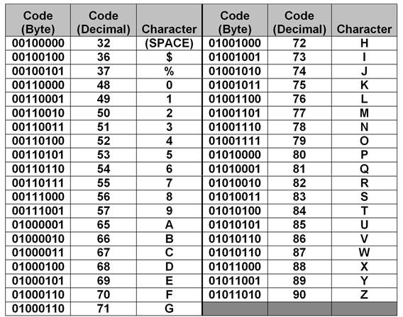
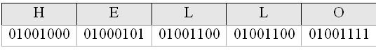
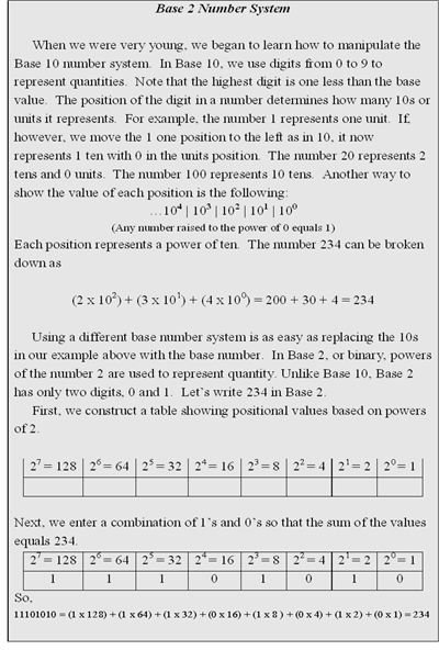
Bits and bytes All information in a computer is composed of bits (binary digits). A bit is a 1 or a 0, represented in a computer’s circuits as the presence (1) or lack (0) of voltage. A collection of eight bits, known as a byte, represents a value in Base 2 (see Base 2 Number System). In order for one device on a network to properly interpret the bytes sent from another device, they must share a common coding format that defines the meaning of each byte value. The most common of these formats is ASCII (American Standard Code for Information Interchange). Windows-based systems typically use this format. Table 1 is a partial list of ASCII codes and the symbols, letters, and numbers they represent. To a computer, the word HELLO would look like the collection of bits shown in Figure 1.
Ethernet packets and MAC addressing
Within a single computing device, ASCII-coded bytes work fine. But when those bytes of data have to move to other devices, we have to wrap some management information around them. This is the function of a network packet. Devices in an Ethernet network use Ethernet formatted packets to exchange data. A sample Ethernet packet is shown in Figure 3.
Each packet is divided into multiple segments. The first segment contains 6 bytes that make up the MAC address of the device to which the packet is being sent. The Source Address segment is comprised of 6 bytes that make up the MAC address of the device sending the packet.
A MAC (Media Access Control) address is a unique identifier written into every NIC (Network Interface Card) by its manufacturer. A NIC is installed in every network device. It’s used to connect a device to the network. Devices on the same network segment use their MAC addresses to communicate with each other. A MAC address is required in addition to an IP address. While an IP address (covered later in this series) is required to get a packet to the proper segment, the packet can’t make the final trip to the target device unless the packet contains the target device’s MAC address.
A MAC address, also known as a hardware address, is composed of 16 bytes. The first 3 bytes are assigned by the IEEE (Institute of Electrical and Electronics Engineers, Inc.) to the manufacturer of the NIC; it uniquely identifies the manufacturer. The last 3 bytes are assigned by the manufacturer to uniquely identify each NIC it produces. Each NIC on a network segment must have a unique MAC address. Duplicate addresses, while rare, are normally caused by manufacturing errors. The following is a sample MAC address expressed in Base 16 (hexadecimal), format:
00-0D-60-3B-4F-88
The Control/Management segment contains 5 bytes that contain the length of the packet, transmission control information, and other low level packet management information that helps the receiving device properly process the packet and return a response to the sending device.
The Data segment contains the actual application or file data. It also contains the information necessary to move a packet between network segments. The number of bytes in this segment varies. It’s determined by network management personnel during setup and optimization of the network. The CRC is a 4 byte value used to ensure the packet is received by the target device without errors. See “How a CRC Works” at the end of this article.
Tables and Figures (Hover for caption, click to enlarge)

How a CRC Works
A CRC (Cyclic Redundancy Check) is a value calculated by both the sending and the receiving device. The sending device runs the packet segments through a program that produces a value. This value, the CRC, is appended to the end of the packet before the packet is sent. When the receiving device picks up the packet, it also runs the packet (without the CRC) through the same program to produce its own CRC value. The receiving device compares the CRC it calculated to the CRC the sending device appended to the packet. If they don’t match, the receiving device knows the packet retrieved from the network was somehow changed or damaged in transit.
Key Terms
Ethernet - The most common local area network standard for exchanging data between networked devices. It defines how packets are sent and received. In Ethernet networks, devices are typically connected to the network via twisted pair copper wire; although fiber cable is often used.
Twisted Pair Cable - Twisted Pair (TP) cable is made of pairs of copper wire. Each wire in a pair is twisted around the other wire in the pair to reduce electrical noise. The most common network TP cable is known as Cat 5 (Category 5). In an Ethernet network, Cat 5 cable is usually installed to support a speed of 100 Mbps (100 Megabits per second or 100 million bits per second). A variation of Cat 5, known as Cat 5e, can support faster speeds. TP cable is less expensive than fiber cable, but’s more sensitive to various types of electrical interference.
Fiber Cable - Fiber cable is made of either plastic or glass. It’s more expensive than copper network cable, but it’s impervious to common types of electrical interference. Fiber cable also supports higher speeds and can be run across greater distances than copper.
This post is part of the series: Introduction to Local and Wide Area Networks
Understanding how networks work is an important first step in understanding information security. This series provides everything you need to know to get started.
- Introduction to Local and Wide-area Networks - Part 1
- Introduction to Local and Wide-area Networks - Part 2
- Introduction to Local and Wide-area Networks - Part 3
- Introduction to Local and Wide-area Networks - Part 4
- Introduction to Local and Wide-area Networks - Part 5
- Introduction to Local and Wide-area Networks - Part 6
- The Importance of Wireless Connectivity