Offshore wind turbines can be much larger than onshore ones, mainly due to a more constant supply of strong wind. The problem area is in the transport to the offshore wind farm location, which requires coordinating the hiring of a specialist heavy-lift crane barge within a suitable weather window.
Offshore Wind Turbines
Introduction
This is the first article in a series on offshore wind turbines. It describes the fabrication and installation of the different steel support structures currently used in UK waters. A second article will follow describing the installation and operation of the actual wind turbine nacelle.
Wind turbines are no longer restricted to onshore locations; there are a number of offshore wind farms currently producing almost 700MW of green electricity.
Offshore wind turbines operate on the same principles as their onshore counterparts, but they are much larger allowing them to have a greater electrical output. This is possible because of the more regular, higher wind speeds which are prevalent offshore, although this comes with a few disadvantages.
The disadvantages are mainly due to the requirement for the coordination of the transporting and installation of the turbines and supports within a suitable weather window with a heavy-lift barge and jack-up crane also required to be hired… but only when the weather is agreeable.
The government allocates offshore areas for the wind farms to be located and contractors wishing to apply for these are required to prepare an extensive Environmental Impact Statement which is submitted to The Crown Estate for approval. I have included a section on this topic in the article and, as you can imagine, this takes a long time to prepare and probably just as long for the Crown Estates to examine the contents. For example The Round 3 allocations of UK offshore areas for wind farms were published in 2007 and the installation of the turbines was approved only last month (January 2010).
However it is a very necessary document in order to protect the marine life, fishing industry, and shipping fleets. Public opinion must be taken into consideration, but a lot fewer people object to offshore wind farms compared to onshore wind farm proposals.
I have based my article on the construction and installation of wind turbines of 5MW capacity, using a monopile support, although either a monopile or a steel jacket support structure can and are being used. I describe how these steel supports are fabricated and installed, with the methods used being similar to the smaller capacity offshore wind turbines, only beefed up a bit.
We shall begin with the fabrication methods of two different types of steel support structures currently in use…..
Wind Turbine Support Structure
The turbine support structure can be in the form of a monopile which is pile-driven into the seabed, a steel jacket structure which is fixed to the seabed using steel piles or suction pads, or a floating support to which the turbine is fixed.
Monopile
This is a single circular parallel column fabricated from 60mm thick steel plates which have been formed in a rolling mill. These rolled sections are butt-welded together around their circumference to make a steel tube which can be 70 meters in length or longer depending on the depth of water.
Once fabricated it then has a numerous sacrificial anode blocks welded to the structure below the waterline.
The monopile is shot blasted and primed with zinc paint, coated with anti-corrosive paint and then epoxy is splattered onto the structure. This extends from the bottom up to the area required for fitting the transition piece, this being given a few coats of zinc paint only. It is then ready for transportation to the wind farm location.
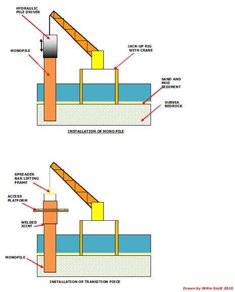
Transition Piece
This is fabricated in the same manner as the monopile and it contains a maintenance platform. The transmission piece has a larger internal diameter than that of the monopile which enables it to slip over the monopile. Once it is in the correct position the transition piece is welded to the monopile.
Installation of the Monopile
The monopile is lifted off the transportation barge by an adjacent jack-up crane and lowered vertically until it is on the seabed.
A hydraulically or air operated pile driver hammer is then attached to the monopile and this hammers the monopile into the bedrock.
The transmission piece is then fitted and welded, the area around the joint being fully corrosion proofed.
Some offshore contractors use a different method of installation by drilling a hole in the seabed into which the monopile is fitted. After installing the monopile into the hole, the gap between the monopile and the hole is grouted using pressurized concrete. This method has the advantage that the monopile can be installed complete with the transition piece.
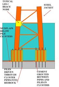
Fabrication and Installation of a Steel Jacket Support.
This has been extensively covered in my previous article entitled Offshore Oil and Gas Platforms, so I will just give a brief description of installation method.
The steel jacket is transported offshore lying horizontally on the barge deck.
The jacket contains integral water and fuel oil tanks in the legs and these are used as ballast tanks, additional temporary ballast tanks being welded onto the legs to assist installation.
Once on location the jacket is floated of the barge, de-ballasted to the near vertical position then further de-ballasted, lowering it onto the seabed. Steel piles are driven through guides at the bottom of the legs right down into the bedrock and grouted using concrete. A transition piece is welded to the structure to facilitate the fitting of the nacelle tower.
The steel jacket support is then ready for the wind turbine nacelle to be attached.
Installation Sketches
This post is part of the series: Installation and Operation of Offshore Wind Turbines
The wind turbines used in offshore windfarms can be of a much greater capacity (3 – 5 MW) than their onshore counterparts. This is due to the supply of a more regular, higher wind speeds which are prevalent offshore, remember the power output of the turbine is the cube of the wind speed.