How to Generate Electricity From Heat, Explained Through Circuit Scematics
Introduction
While shuffling through my old engineering books, I luckily found this piece of paper which had very interesting information regarding how to convert waste heat into electricity (although in small amounts). Probably it was plucked by me from some electronic magazine a long, long time ago. Since the bottom portion of it was quite battered, I couldn’t identify the name of the magazine, but fortunately the authors name and the whole article was intact.
Developed by J. Freshwater and C. Sanjay, the idea deals with an innovative way of exploiting the natural characteristic of the not so popular semiconductor device – the tunnel diode.
The concept is somewhat tough and it took quite some time for me to actually grasp the whole procedure. But don’t worry- I have arranged the whole circuit evaluation into an easy to understand explanation just for you.
Let’s go through it.
How the Concept Works
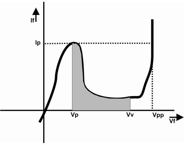
A tunnel diode is hugely different from a normal rectifier diode and is characterized by a fast response time. Also referring to the graph we find that, as the applied current IF is increased, after a certain value, astonishingly its forward voltage UF dips, quite unlike other normal diodes. Thus it clearly shows a negative resistance characteristic (shown by the shaded area) and basically is exploited for the present purpose of generating electricity from heat. This characteristic is normally represented as – Rd.
Now, according to Ohm’s Law, in an electric circuit loop consisting of a battery and a load, I = U/R, where I is the current, U is the applied voltage and R is the resistance offered by the circuit load. Obviously here the positive sign associated with I and R indicates that the battery will start discharging through R. Therefore conversely, if I and R carry a negative sign or a minus sign, theoretically and logically, it should start charging the connected battery.
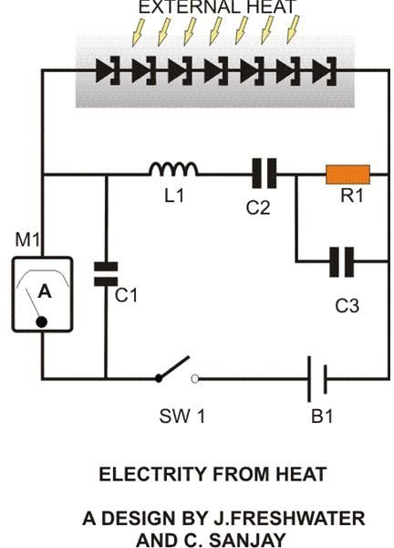
Going by the above explanations, consider a closed loop circuit consisting of a chargeable Ni-Cd battery and a group of tunnel diodes (see figure and click to enlarge). If we apply heat externally to these diodes so that their IF increases to the desired level (– Rd) , the resultant Ohm’s law can be now derived as:
– I = U/– R. Also, the dissipated power will look like:
P = – I2 – R (by substituting Ohms law in P = IU).
The above expression convincingly proves that the circuit is now in fact charging the battery.
Interestingly here, the load itself acts as a voltage source with a low internal resistance. However, the generated voltage should be greater than the battery voltage to initiate the charging current. The charging current IC is expressed by the following equation:
IC = δ[Ʃ(UF) – (Ubat)]/Ʃ(Rd)+Rbat
In the above equation Ʃ(Rd) notation indicates that all the diodes involved in the circuit need to be operated specifically at their – Rd region and if any diode does not satisfy this condition it would simply cancel the whole objective of the concept. So it becomes imperative to carefully segregate these diodes by testing each of them individually so that the circuit is able to produce the desired function of generating electricity from heat.
How to Test the Diodes Discretely?
A simple test circuit set up (see figure and click to enlarge) makes the segregations very easy. It will be important to note that the ammeter used in the circuit should
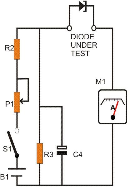
be able to indicate both the positive and the negative current polarity of the diodes under test. Also, the whole operation needs to be performed at an ambient temperature that’s below 8 degrees Celsius. The procedure is completed with the following steps:
As shown in the schematic, connect the diodes one at a time into the given slot.
Slowly adjust the potentiometer and record their UF/IF response and make sure they produce the desired (– Rd) result.
You will need to keep a FM radio close to the set up during the present procedure. Tune the radio to around 94 MHz, keep the volume fairly loud. Make sure that the diodes under test do not oscillate at the tuned frequency (due to the Gallium-Indium Antimonide doping in Tunnel Diodes: 10-7).
The above response may vary a bit for different diodes between 200mV to 260mV; group them such that this value is as similar as possible for each of them.
Also, adding up of the above voltage of the selected group should produce a greater value than the battery voltage that is to be charged. For example if the average UF of the selected group of tunnel diodes comes to about 210mV, then we may require 7 such diodes to effectively convert waste heat into electricity and charge a 1.2 volt Ni-Cd cell.
Parts List
All Resistors are 1/4 Watt, 5%, CFR.
R1 = 20 Ohms,
R2 = 56 Ohms,
R3 = 33 Ohms,
P1 = 2K2 PRESET, LINEAR,
C1 = 20 n,
C2 = 820 pF,
C3 = 1.5 nF,
C4 = 10 u F,
L1 = 2.2uF, 5 turns of 22 SWG enameled copper wire, 7mm in diameter, air cored,
B1 = 1.2 V Ni-Cd CELL,
M1 = 100 MA FOR MAIN CIRCUIT.
M1 = 1 MA FOR DIODE TEST CIRCUIT.
TUNNEL DIODES = BA 7891 NG
GENERAL PURPOSE PCB, ALUMINUM PLATE ETC.
Construction Clues
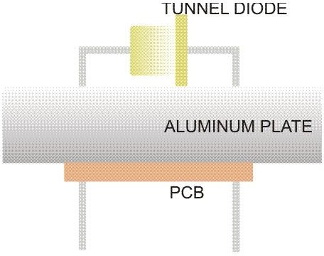
Once the required diodes are appropriately selected, the construction may be commenced by fixing all the 7 diodes over an aluminum plate, observing due care not to short circuit their leads with the metal as shown in the figure. Next, assemble the rest of the shown components over a general purpose PCB with the help of the circuit schematic and connect the relevant points to the diode series. The circuit is now complete.
If now an ammeter is connected to the circuit as shown, and if the ambient temperature is over 35 degrees Celsius, you should immediately start witnessing some deviation over the meter, indicating the conversion of heat into electricity. If the diode/aluminum plate assembly is introduced to some more significant source of heat, like from direct sunlight or near a furnace, the rise in the charging current may rise as high as 100 mA, quite enough to charge the single Ni-Cd cell within few hours.
The above idea, though a bit complicated and miniature, introduces quite an impressive method to convert waste heat into electricity, which always seemed pretty illusive to everybody.
Related: Stirling Engine Revival - Using Stirling Engines to Recover Waste Heat in Mechanical Engineering