As the central point of installation for all of your computer’s internal parts, the system motherboard is the most important part of the computer system aside from the microprocessor and memory modules. So how do you know which part goes where?
Introduction
As the central point of installation for all of your computer’s internal parts, the system motherboard (or alternately mainboard, mobo – or even logic board, in the case of an Apple machine) is the most important part of the computer system aside from the microprocessor and memory modules. Serving as the means for the flow of information between the various parts connected to its circuitry, the motherboard provides the means to connect the system’s internal parts while transmitting signals back and forth thereof from and to these parts, thereby resulting in an operating, fully-functional computer system to handle all your everyday tasks.
So the question is, when swapping parts or building your own computer system, how do you know which part goes where – and what, then, do said parts look like when you go to match them to their connection points? In this guide, I will provide a visual representation or two of the layout of a typical computer motherboard, along with images of the various parts used on the motherboard itself to provide a reference thereof as to the various parts that make up the inner workings of your computer system.
Understanding the Motherboard Layout
Understanding what goes where is part of the process of understanding which part of the motherboard does what. By analyzing and understanding these sockets, ports and so forth the maintenance and installation of computer parts becomes easier to understand.
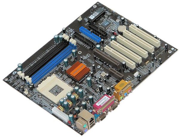
The images in this section represent examples of typical computer motherboards. The image on the left represents a typical example of a recent
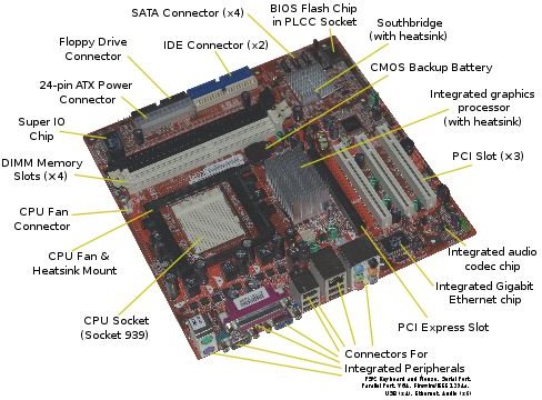
motherboard, while the image to the right represents a generic motherboard layout with the individual components and ports labeled for clarity.
In the following sections I will explain further what each individual section of the motherboard entails regarding where everything goes when adding parts on top of the motherboard.
(Upper Left: A typical motherboard design with the most relevant features currently available, image credit: Wikimedia Commons/Darkone . Lower Right: A generic motherboard design with the individual sections labeled, image credit: Wikimedia Commons/Moxfyre .)
Central Processor Socket

Obviously you can’t have a computer system without something running the show, and the computer’s central processor (often referred to as the CPU or a microprocessor) is traditionally considered to be the brains of the entire operation. In the labeled-parts image, the CPU socket is the grayish-white unit within a black outer border; on modern motherboards, this socket is commonly set up for easy-installation. Of course, when installing the CPU it pays to align the corners properly as the socket can tell if you’re trying to put it in backwards; so if you’re up against socket resistance then you’re obviously doing something wrong. Usually the notched or dotted corner (as shown in the image to the left) is the key to a successful installation, so take note of this marking and plan accordingly.
The aforementioned black border area functions as a mount for the CPU heat sink, the installation of which is a necessary part of any computer system as it helps to cool down the system; leaving this part certainly has some rather dire consequences. Installation of a fan unit on top of the CPU further degrades the heating of the computer system, and should also not be overlooked; additionally the CPU fan needs to be plugged in to the marked power port on the motherboard in order to function, as shown in provided image.
Other types of processors and similar chipsets exist as well; however, these are usually built into the motherboard and are generally not user-replaceable. These include the southbridge unit, integrated graphics processor and Ethernet units, and the onboard sound processor.
(Section Image: Example of an Intel Core2 Duo microprocessor; image credit: Wikimedia Commons/Simial .)
Memory Module Slots
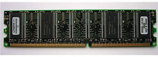
Concurrently with the CPU, the memory slots function to drive the system through its paces; installing these is a definite must-do as well. Memory Units are generally installed in pairs, and typically come in the form of DIMM modules (usually according to the most recent DDR standards). Memory modules serve to hold information that is currently in use by the computer system; once finished with the information, the information is wiped from these units – in fact, when the computer shuts down, these units are wiped completely.
On current motherboards, there are four slots for the installation of these memory units, and are normally sold in capacities of one, two, and four gigabytes or more. The bigger the capacity, the more space there is for processing information – and hence the faster your computer runs. One downside to higher capacities is the general limits of the CPU itself, concurrently with your computer software: if you only have a 32-bit operating system and/or CPU installation, you’re only going to be able to use a maximum of approximately three gigs worth of your memory module capacity.
(Section Image: Example of a DDR-SDRAM DIMM, a fairly recent type of memory module; image credit: Wikimedia Commons/ J-P Kärnä .)
Power Connector Port
This port, which is usually a twenty-four pin connector, serves as the input for the computer power supply; if the computer manufacturer uses anything else (as formerly applied by companies like Dell and HP) you may only be able to use power supplies from the computer manufacturers themselves. On the other hand, that proprietary connector practice is beginning to fall out of favor so this may not apply to you but suffice to say that if you do have such a computer system then you’re basically S.O.L. when it comes to switching power supplies and motherboards.
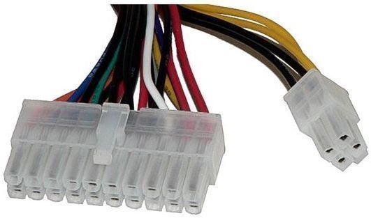
On the other hand, if you used the computer industry’s equivalent of a “chop shop” (IBuyPower and CyberPower PC are good examples, especially for people who are planning on playing a lot of power-hungry games on their computer systems) then such a case (both metaphorically and literally ) isn’t going to be an issue; nonetheless I have to make note of it as the issue does exist for the general-purpose computer manufacturers. Either way, the procedure is exactly the same: all you do is plug in the multi-wire cable running off from the power supply, and that’s it. Once the remaining parts of the system are in place, the computer is ready to be switched on. Simple as that.
(Section Image: An example of a typical multi-wire ATX power supply motherboard connector, image credit: Wikimedia Commons/Ivob .)
Expansion Card Slots
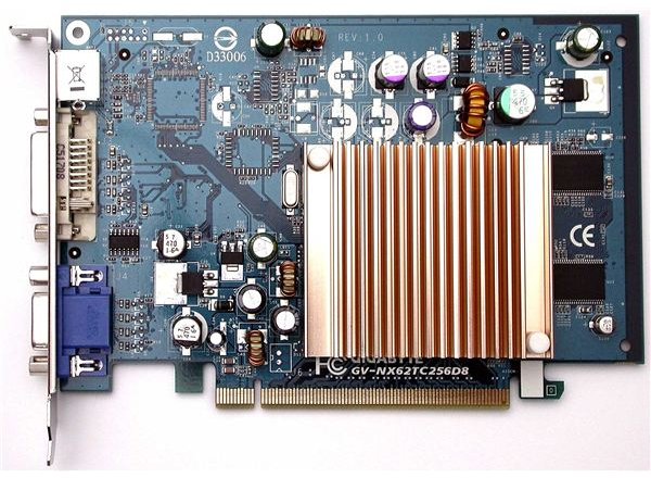
The expansion card slots function as the means to install various system components that are designed to plug directly into the motherboard in order to enhance the capabilities of the computer system. Among the most common uses for this type of system component installation are specialty video processor boards and sound cards, as well as installing additional USB ports, Ethernet adapters and even television signal processors. There is a general total of four expansion card slots; however, this may vary somewhat types of expansion slots thereof based on the age of the motherboard.
Generally, some of the more common types of expansion cards use the traditional PCI standard; however, in the case of video processor cards installed into the expansion slots it is necessary to use an entirely different type of expansion card, which generally plugs into an entirely different type of expansion slot (such as the old AGP standard, or the newer 16-speed PCI Express slots). Additionally, as PCI Express slots become more common on newer computer systems as additional types of components move over to the new standard, so too does the general layout of the expansion card installation points on the motherboard. As such, what you see today will undoubtedly be very different on computer motherboards in the future.
(Section Image: An example of a typical 16-speed PCI Express video card with the graphics board’s parts exposed; image credit: Wikimedia Commons/Clemens PFEIFFER .)