We cover how to install a motherboard in SFF and tower cases.
Preparing Your Case for the Motherboard
Whether you already have the power supply in or not, you will install the motherboard in largely the same way. The first step is to
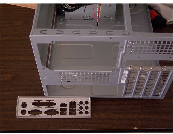
remove the I/O panel protector included with the case if your case came with one. If not, skip to the next paragraph. The protector is located at the rear of the case. Just push and tap from the outside until it pops out (out of the hole where it is, but into the case). I am not sure why they even include these with the case as you just have to take them out to use the one that comes with the motherboard.
If you haven’t yet, open the box your motherboard came in and use the manual to make sure you have everything that should be there.
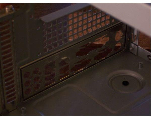
Take the I/O panel protector that comes with your motherboard, make sure it is right-side-up and right-side-out, and press it, from the inside, into the hole from which you removed the one that came with the case, or the hole indicated by your case’s instructions. This can be a little tricky; if you find you can’t get one or two corners in, try pressing them in with a flat headed screw driver. The pictures indicate the case before and after the panel is installed, from outside and inside of the case, respectively.
Preparing the Motherboad Tray
Have a look at the motherboard tray, the area where you will attach the motherboard. This is the side across from the one you opened
earlier in a tower, and usually the bottom in an SFF. If you are working on a tower, place it on its side so you can work on the motherboard tray from a top-down view. Note that motherboard trays are removable in some cases, and following your case’s instructions to remove the tray before installing the motherboard and reinserting the whole thing can be easier than trying to install the motherboard directly in the case, if you have the option.
On the motherboard tray there will be screws with threaded sockets as heads (standoffs) that accept other screws, as well as holes where you can place more of these standoffs. Your motherboard will rest atop the screws with holes (called standoffs since they allow the motherboard to not touch the metal tray underneath it, which would cause a short circuit). Round-headed screws, not case screws, go through holes in the motherboard and into the standoffs. If there is any doubt about which screws to use, make sure they fit into the standoffs by testing one; you should be able to get the screw started in the standoff easily and without a screw driver.
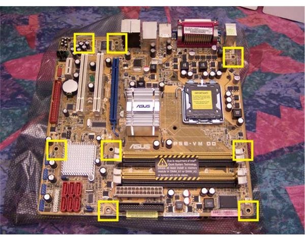
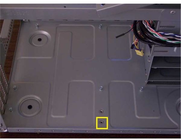
Note that like screws, all holes are not created equal. The holes used to attach the motherboard to the standoffs, such as the ones in yellow squares on our picture of the ASUS P5E-VM DO, are insulated from the motherboard circuitry. We need to make sure there is a standoff under each of these insulated holes. Some of these will already be installed, screw in the remaining ones. We also need to make sure there are no standoffs in other places, they could touch the mobo in the wrong spot and cause a short. Unscrew those.
Your manuals are useful here, as they are all along. The one for the mobo will include diagrams as to exactly which holes need standoffs. The one for the case will let you know if there are any extra steps to take before the motherboard goes in. For instance, some cases have bulges under the motherboard and they include plastic or rubber stickers you apply to keep the metal bulges from touching the board, again to prevent a short. In our case, we just need to add one standoff in the hole marked by the yellow square in the picture of the motherboard tray at the beginning of this section.
In Goes the Mobo
This probably goes without saying, but unlike the hunks of metal you have dealt with so far, the motherboard is a delicate piece of electronic equipment. Make sure you are grounded or at least touch a big metal thing to make sure you don’t give your motherboard an expensive static shock. Remove it from the static proof bag and inspect it for obvious physical damage, front and back.
Orient the motherboard correctly; its connectors (where you will plug in things like your keyboard later) should face the I/O panel you installed earlier. In our case, that is the top left as pictured. Line up the connectors with the panel and slide the board towards the rear of the case. Note that there are lots of little flanges and tabs on the I/O panel that are meant to fit over or around the motherboard connectors. Make sure these are all in place and that none are actually in the connector they are meant to protect. If one is in the way when you slide in the board, it could do some serious damage.
The holes in the motherboard should now be right above the standoffs. Starting from the middle-most holes then working from corner to
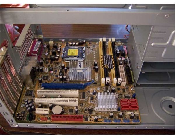
corner diagonally (same as you would if you were doing some carpentry, upholstery, etc.), and using the correct screws mentioned earlier, screw in the motherboard. You want the screws to be very snug or slightly tight; over tightening can damage the mobo. It only needs to handle fan vibration and you occasionally moving the system around, so don’t screw it together the way you would a trampoline for elephants.
Make sure you put a screw in each hole indicated by your manual, and if you drop any in the case make sure you get them out since they can touch the wrong thing and, you guessed it, cause a short. If your screws are all where they should be, get excited, we are about to give our Frankenstein a brain; that’s right - in the next article we will install the CPU!
This post is part of the series: Building a PC
We show you how to build PC, step by step, with pictures.
- Building a PC: Open Your Case and Get to Work!
- Building a PC: Time to Install the Motherboard
- Building a PC: Installing a Core 2 CPU
- Building a PC: How to Install a Power Supply Unit
- Building a PC: Installing Memory
- Building a PC: Installing an Optical Device
- Building a PC: Installing a Hard Drive
- Building a PC: Installing Graphics and Other Expansion Cards
- Building a PC: Installing Fans
- Building a PC: Power Connections for the Motherboard and Fans
- Building a PC: Connecting the Hard Disk and Burner
- Building a PC: Connecting the Case’s Switches and Audio
- Building a PC: Connecting the Case’s Front Panel Ports – USB, Firewire, and eSATA
- Building a PC: Closing the Case
- Building a PC: Connecting Peripherals