Even the most stripped, budget, case has a couple lights and switches to hook up. These are tiny little wires that go on tiny little pins. The good news is you’re almost done building your PC.
The Basics
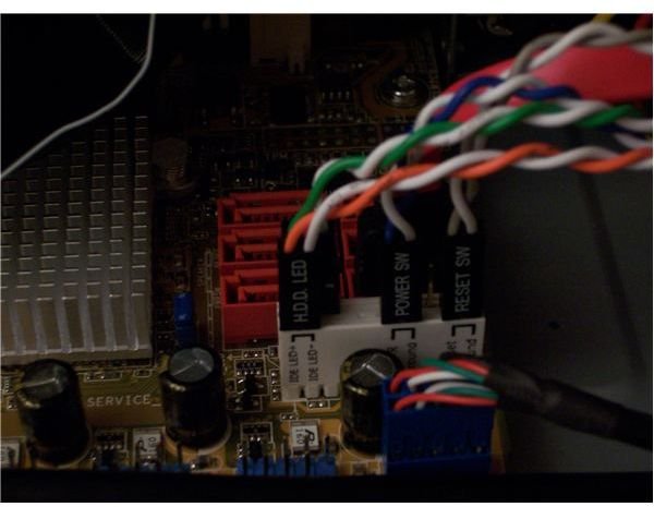
The front panel of your case has a bunch of stuff you need to connect to your motherboard. Most crucial is the switch that turns the PC on and off. This, along with the reset switch, as well as the power and hard drive activity lights, are plugged into a group of pins on your motherboard. Their location and functions will be outlined in your manual.
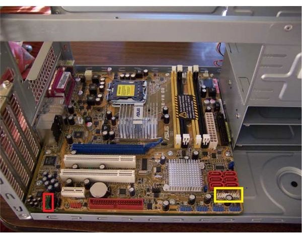
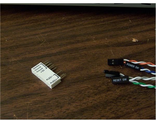
On the ASUS P5E-VM DO pictured, the pins are in the lower right, in the yellow rectangle (the red rectangle points out the audio connectors used in the next step). Another, more differentiating, feature of ASUS’ motherboards are what they call the “Q-connector”, pictured below. This allows you to hook up these tiny cables and pins where you can see and reach them, then plug the single larger connector into the motherboard. It also makes your life much easier should you need to un- and re-hook the wires for whatever reason. If your mobo lacks this kind of feature, just use it and your case’s manuals along with the writing on the connectors and near the pins to make the connections one at a time.
ASUS Q-Connector
Audio
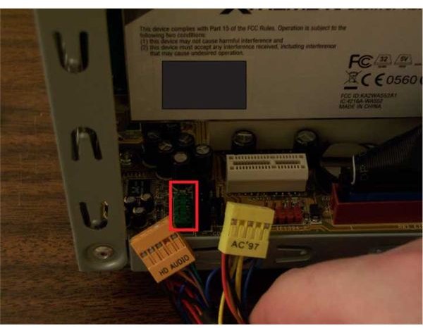
As the picture to the right shows, this case has both AC ’97 and HD Audio connectors. Use the one indicated by your motherboard manual. If you have a choice, HD Audio is the newer and superior option. There is a missing pin and blocked hole to help you get the orientation right. If you are using a sound card and want to hook up your front panel audio to it, the process will be quite similar. If you have any concerns, check your sound card’s manual.
And More
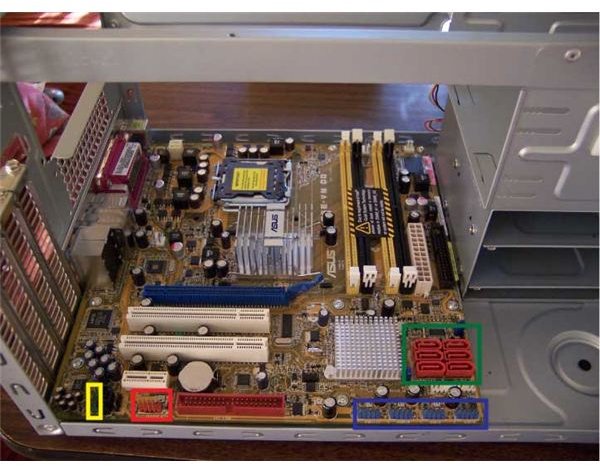
Almost all cases today come with some connection ports along the front. The locations on the motherboard to where they connect are picked out with coloured rectangles in the picture. Most common are the Audio Mic-In and Headphone-Out (yellow) we just attached along with a pair or two of USB ports (blue). Some cases sweeten the pot with Firewire (red) or eSATA (green) connections. A built-in card reader usually functions via a USB connection; it will probably connect in the same way as a USB port, check your manual if you have any doubts.
We make the USB, Firewire, and eSATA connections in the next article.
This post is part of the series: Building a PC
We show you how to build PC, step by step, with pictures.
- Building a PC: Open Your Case and Get to Work!
- Building a PC: Time to Install the Motherboard
- Building a PC: Installing a Core 2 CPU
- Building a PC: How to Install a Power Supply Unit
- Building a PC: Installing Memory
- Building a PC: Installing an Optical Device
- Building a PC: Installing a Hard Drive
- Building a PC: Installing Graphics and Other Expansion Cards
- Building a PC: Installing Fans
- Building a PC: Power Connections for the Motherboard and Fans
- Building a PC: Connecting the Hard Disk and Burner
- Building a PC: Connecting the Case’s Switches and Audio
- Building a PC: Connecting the Case’s Front Panel Ports – USB, Firewire, and eSATA
- Building a PC: Closing the Case
- Building a PC: Connecting Peripherals