Our PC has taken shape; in this article we connect the drives.
Connecting a Molex Powered PATA Device
We put the burner in the case in this article ; now we are going to hook it up. If you haven’t physically installed the device yet, go check that article and come back: don’t worry, we’ll wait. Done? Good.
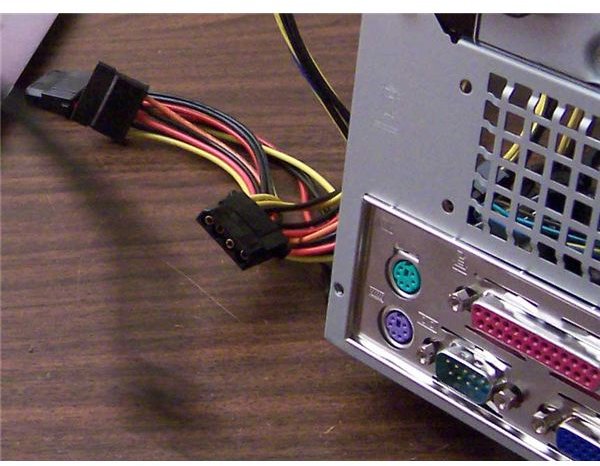
First we’ll hook up the power. PATA (Parallel Advanced Technology Attachment) devices, like the disc burner pictured, draw power via a 4-pin molex connector (also pictured). Note that two of the corners are angled, so it will only fit one way.
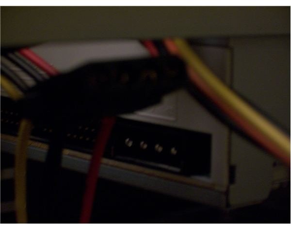
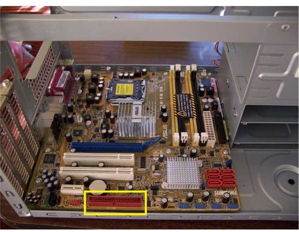
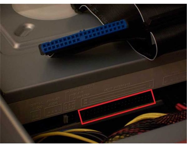
Now for the data cable: this ribbon can interfere with airflow rather noticeably, so try to keep it away from fans and vents. The first picture below shows the connector’s location (in yellow) on the motherboard. The second is a close up the ribbon connector and where it goes in the optical disk (red rectangle). The notching only allows the cables to go in one way, but note that the blue end of the ribbon goes in the motherboard, and the black end in the drive.
PATA Data Connection
Connecting a SATA Device
Again, we assume the hard disk is already in the case. If you haven’t done that yet, we cover it in this article.
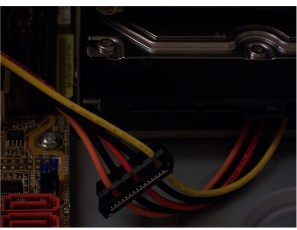
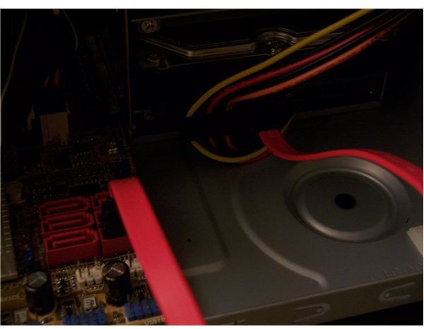
Power is delivered by the connector pictured below. It only fits in one way. Data travels by a cable (shown in the second picture) which is much smaller and easier to work with than the wide PATA ribbon. This cable’s ends also fit only one way, but either end can go either in the motherboard or drive.
SATA Connection
Cable Wrangling
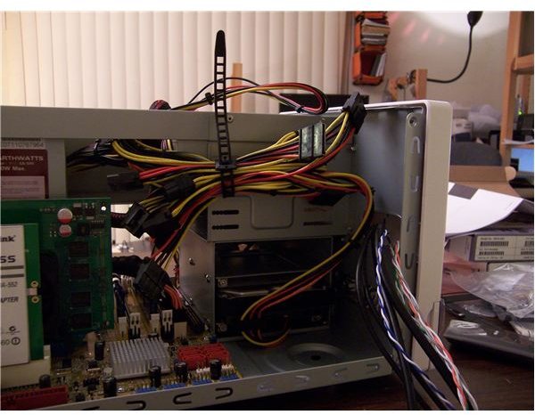
The final picture shows how we dealt with unused and slack power cables. Using a reusable tie that came with the PSU, we bundled them all together. Using the self-adhesive clips that came with the case, we hooked the bundle to the side of the optical drive cage, where it is relatively out of the way of equipment and airflow. Congratulations, the PSU installation is complete!
The wires coming out of the case at the right of our picture connect the case’s front panel switches, lights, and ports to the motherboard. We perform this step in the next article.
This post is part of the series: Building a PC
We show you how to build PC, step by step, with pictures.
- Building a PC: Open Your Case and Get to Work!
- Building a PC: Time to Install the Motherboard
- Building a PC: Installing a Core 2 CPU
- Building a PC: How to Install a Power Supply Unit
- Building a PC: Installing Memory
- Building a PC: Installing an Optical Device
- Building a PC: Installing a Hard Drive
- Building a PC: Installing Graphics and Other Expansion Cards
- Building a PC: Installing Fans
- Building a PC: Power Connections for the Motherboard and Fans
- Building a PC: Connecting the Hard Disk and Burner
- Building a PC: Connecting the Case’s Switches and Audio
- Building a PC: Connecting the Case’s Front Panel Ports – USB, Firewire, and eSATA
- Building a PC: Closing the Case
- Building a PC: Connecting Peripherals