The constant change in the position of the sun throughout the year has posed quite a big challenge for us as far as solar power harnessing is concerned. Building solar trackers may seem difficult, but the simple solar tracker controller mechanism idea presented here will prove this wrong.
Introduction
The best thing about solar cells obviously is their ability to convert sunlight into electricity. Because sunlight is unlimited, this form of electricity is abundant, free of cost, and may be received almost from any part of the world. But sadly, solar cells become quite useless in the absence of sunlight, i.e. during overcast conditions.
Of course, we have found ways to overcome this situation by using batteries, converters, and a backup generator , but the problem doesn’t end there. The performance of these converters and panels very much depends on the angle of incidence of sunlight. They are able to generate maximum power only as long as the light rays are perpendicular to the panel’s surface. Since the position of sun is never stationary, the angle of the light rays changes with time, and therefore the efficiency of the solar cells is also reduced proportionately. Thus, even after having all the means we become quite helpless in utilizing them effectively.
People have tried to find a remedy by installing extra solar panels at different angles. This solution too has its own drawbacks, like, very high initial costs, wide variations in the input power and less than 50 % of the units actually get utilized at a particular instant.
A simple construction idea of a dual-axis solar tracker system presented here should take care of the above problem very effectively.
Building solar trackers may seem very complex, but as we will see, the proposed idea is not only easy to understand, but also provides a comprehensive solution for tracking the sun as desired.
Parts List
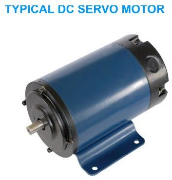
The mechanical parts of this solar tracker are all made to order and will very much depend on personal specifications. The type and rating of motors used is also matched as per the size and weight (load) of the assembly.
The electronic components required for the controller circuit are as follows:
All resistors are ¼ watt CFR 5% unless otherwise stated.
R1, R2, R3 = 1K,
R4, R5, R7 = 100K,
R6 = 2M2,
C1 = 0.1µF/50V,
P1, P2 = 100K, PRESETS,
T1, T2 = TIP 31,
T3, T4 = TIP 32,
DI = 1N4007,
ALL MOTOR DIODES ARE IN5402,
IC1 = 4093,
IC2 = 4060,
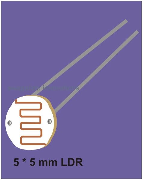
LDR1, 2 = 10K AT FULL ILLUMINATION, INFINITE AT COMPLETE DARKNESS,
S1, S2 = HEAVY DUTY PUSH-TO-ON SWITCHES,
GENERAL PURPOSE AS PER SIZE,
SUNDRIES: WIRE, ENCLOSURE, SCREW/NUTS, SPACERS ETC.
The next page will deal with a straightforward procedure for building a solar tracker mechanism.
Image Source:https://www.alibaba.com/product-gs/292401881/12V_100W_1200W_DC_Electric_Motors.html
Mechanical Assembly
Please note that the following is an engineering design idea and has not been tried practically. I think that once you read the entire article, you will agree regarding this concept’s high feasibility. With the help of the given diagram (click to enlarge), the complete mechanical working of this two-axis solar tracker can be understood as follows:
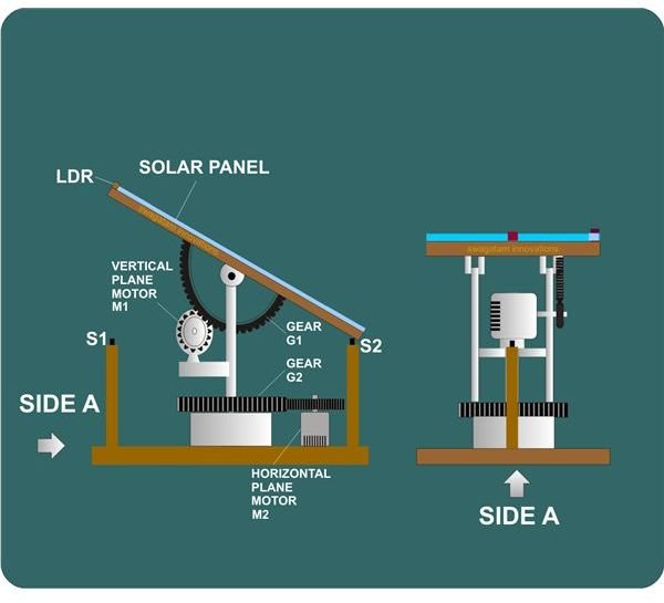
- We see that, broadly, the tracker is made up of a strong wooden base over which the whole assembly has been fitted.
- The solar panel’s base is also wooden and is clamped to a rigid metallic frame through a couple of sets of movable hinges. It is so arranged that the panel is free to move through complete 90 degrees over its fixed central axis.
- The bottom surface of the solar panel’s base carries a large gear G1 fixed over it, resembling an inverted “D.”
- An electric motor M1 is mounted and clamped firmly over a metallic extension coming out of the metallic frame itself.
- The motor spindle also carries a gear and is appropriately integrated mechanically to the above explained “D” shaped gear G1. The rotation of the motor makes its gear interact with the gear G1 and forces the solar panel assembly to move radially over the vertical plane.
- Thus, the activation of this motor results in the shifting of the solar panel through 90 degrees on both sides.
- The above function takes care of the solar panel movement on one axis or on the vertical plane.
- As we all know that the cycle of sunrise and sunset not only alters continuously throughout the day, but also changes with season. This makes accurate tracking pretty difficult over a single axis. Therefore, the system should be able to track the sun over the horizontal plane also i.e. laterally.
Let’s study how this dual-axis solar tracker is made to move laterally or on the horizontal plane:
- The metallic frame supporting the solar panel is screwed at the bottom over a heavy gear G2 and a cylindrical base pivoted at the center of the wooden base.
- A second motor M2 fixed beside the above assembly also carries a gear over its spindle and its teeth are locked appropriately with the larger gear G2.
- When this motor is activated, the gear G2 also activates and begins moving the entire solar panel assembly laterally and has a freedom of rotation of 360 degrees, back and forth.
- Thus we see how the whole mechanism of this two-axis solar tracker is able to maneuver and track the sun rays on both the planes very effectively.
But the above assembly can carry out the said function properly only after receiving correct commands from an “intelligent” solar tracker controller. This controller should be able to follow the varying positions of the sun, sense its light rays, and convert them into the relevant signals so that the appropriate motors are activated.
The explanation provided on the next page will show how through a simple electronic circuit the above mechanism is brought to life.
Circuit Description of the Controller Circuit
The points below will clearly explain how the proposed electronic solar tracker controller circuit works:
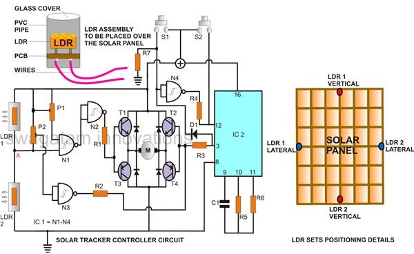
- Referring to the circuit diagram (click to enlarge) we see that the entire circuit is built around the gates N1-N4 of IC 4093 (Quadruple 2 Input NAND Gate, Schmitt Trigger).
- N1, N2, and N3 are all wired to form a window comparator. It monitors the voltage at point “A” and keeps it within a particular range set by P1 and P2.
- The voltage at point “A” will vary only when the light intensity falling on the two LDRs are not equal, i.e. when the sun rays are not perpendicular to the solar panel’s surface.
- Assume that the light falling over LDR1 reduces its resistance sufficiently and crosses the higher reference level set by P1.
- Point “A” becomes high enough to trigger N1 whose output instantly goes low turning ON the driver transistors T1, T3 through N2. The motor M1 connected to the transistors activates and adjusts the solar panel so that it faces the sun rays at 90 degrees. The LDRs now also receive equal light intensities, point “A” potential returns back to the set window level and the motor deactivates.
- Now suppose the whole set up is positioned the other way round, i.e. opposite to the position which may produce the above explained situation.
- Here, as the sun drifts, at some instance the light falling over LDR2 will cross the lower reference level set by P2. The level at point “A” will fall enough to make the input of N3 go low. Its output will invert to activate transistors T2, T4 and the motor. The motor rotates, but now in the opposite direction to correct the tilt of the solar panel until everything is back to normal.
The above two operations will enable the system to track the sun over a single plane only i.e. on the vertical plane.
To make the system track the sun laterally, another set of the above described solar controller circuit will have to be employed.
The circuit operation will be exactly similar to the above explanation. But in this case the second motor M2, fixed over the wooden base will be activated and will correct the position of the solar panel over the horizontal plane or laterally. This operation will be very gradual and slow and a substantial shift can be identified over many months of time.
From sunrise to sunset the system will faithfully track the sun until it becomes dark. But, darkness would also mean the LDRs are subjected to equal levels of light, and the tracker would get stranded in that position until the next morning. But even after the sun rises the next day, the system will be totally unable to sense the light as it would be facing in the opposite direction then. The problem is solved by introducing switches S1 and S2 and is explained as follows:
As the sun is about to set, the solar panel is deflected to a position which toggles switch S1. S1 immediately initiates a timer comprising of IC2 and the associated parts. The timer counts (set by C1 and R5) and waits for some time after which it sends out a command to the motor M1. The motor M1 activates and moves the solar panel back all way round to its original position facing eastwards. The moment it reaches to its ready position, switch S2 is triggered which switches the timer OFF. The next day the whole procedure repeats itself.
The circuit is easily built by fixing the components over a general purpose PCB and interconnecting their leads by soldering as per the circuit schematic. The entire circuit is then housed inside a weather proof enclosure, allowing the appropriate wires for the LDRs and the motors to come out of it.
The LDR assembly is also done as per the diagram.
Calibrating the Circuit
Once the solar tracker controller circuit assembly is completed correctly, calibrating it is very easy and is done with the following steps:
- Over a flat table, place the LDR assemblies (connected to the circuit) with a separating distance that would exactly match their positions over the solar panel.
- Position a light source somewhere at the top in between these two LDR assemblies.
- Connect a small bulb in the place where normally the motor would be connected.
- Shift the position of the light source more towards LDR1; adjust P1 so that the lamp connected in place of the motor lights up. Now, bring the light source back to the center, and adjust P1 so that the lamp just shuts OFF. This sets the anti-clockwise tracking of the solar panel.
Similarly, the clockwise tracking set up of the solar panel may be done by shifting the light source more towards LDR2 and back to the center and by adjusting P2 during the process as above.
This concludes the construction and calibration procedure of the solar tracker unit. The wiring and integration of the mechanical devices with the electronic controller may be done through some personal technical knowledge, and I will leave it to the readers. If you have any questions, please add your comment (comments need moderation and may take time to appear).
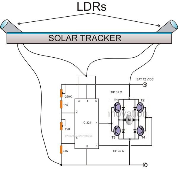
Simplified Circuit Update
Upon further study regarding the above discussed topic, I came up with a simpler circuit using op amps that should probably function in a much efficient way. The circuit in this section simply proves the its simplicity. Moreover, the switches S1 and S2 as discussed in the article can be eliminated if the LDRs are smartly positioned as shown in the adjoining figure. Remember you will have to build two such identical circuit and LDR set ups for the vertical and the lateral tracking movements respectively.