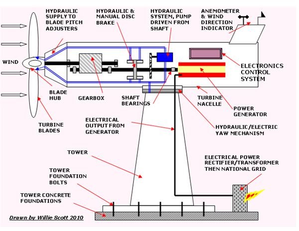
A Horizontal Axis Wind Turbine (HAWT) produces renewable electrical energy to the grid. The blades which face into the wind rotate, driving a gearbox, power generator, hydraulic system and electronic controller contained in a nacelle, supported on a high steel tower fixed into concrete foundations.
Introduction to Wind Turbine Components, Operation and Installation
Wind is formed by a combination of the earth’s rotation and solar energy which heats the air causing it to rise. The air cools and falls again forming thermal convection currents – the source of the wind.
Because this is a sustainable activity, any machine which exploits the energy from the wind is classed as a renewable energy device, with wind turbines being one such appliance.
The turbine unit consists of a hub which houses three blades and drives a power generator through a gearbox contained in a nacelle. The nacelle is attached to the top of a steel support tower which is bolted to concrete foundations in the ground.
The power generated is normally fed by cable down the inside of the tower, exiting at the bottom into a rectifier or transformer.
There can be numerous wind turbines connected together to form a wind farm, producing many megawatts of green power for the national grid, or just one or two supplying a local community.
In this article, the second in the series on renewable energy, we shall examine how Horizontal Axis Wind Turbines (HAWT) operate and are installed in an onshore wind farm.
The Rotor Blades
There are normally three fiberglass-reinforced polyester blades, up to 20m long that are connected to the central hub, extracting the kinetic energy from the wind.
The hub contains the electrohydraulic motors used to change the angle (known as the pitch) of the blades to the wind, which can then alter the blade rotation. The blades rotate slowly, usually between 10 and 20 rpm in wind speeds of 5 to 15 m/s.
The Nacelle
This contains all the components essential to the efficient operation of the turbine. It is fitted at the top of the tower and maintains the blades facing the wind by an electric/hydraulic yaw unit at its connection to the tower, operated by the electronic controller.
A wind speed anemometer and a wind vane are mounted on the nacelle tail as is sometimes also a lightning conductor. The speed and direction of the wind data is fed to the electronic controller which adjusts the blade pitch and yaw accordingly.
The Gearbox
The gearbox is used to increase the revolutions from the main drive shaft to the power generator drive shaft. Depending on the type of generator and the number of poles used, an input speed of say 15 revs/min can be increased to 1500revs/min.
Wind turbine drive mechanisms can also have a direct drive system which uses variable blade pitch, thus avoiding the use of the gearbox and giving a quieter operating system.
Drive Shafts & Brake
These are a hollow or solid steel hardened shaft under very high stresses and considerable torque. There are normally two shafts; the gearbox input drive shaft from the blade hub, and the gearbox output shaft which drives the power generator. The gearbox output shaft also drives the hydraulic system and, incorporates a hydraulic and manual disc brake system which is used during turbine maintenance.
Power Generator
The length of the turbine blades along with the wind speed determines the output of the power generator, most of which these days produce AC power instead of the previous DC. This was suitable for battery charging systems, but had to be rectified to AC before supplying the grid.
Nominal generator output for wind–farm turbines is continuously increasing as it is more economical to use a high output generator, the usual generator capacity nowadays range between 1 and 2MW. (A recent installation to the Beatrice oil field in the North sea has two 5MW turbines providing power to the field offshore installations)
The power produced by the wind farms is fed to transformers and then onto the National Grid.
Wind power is not a constant supply therefore it is used as back-up to the existing fossil fueled, hydro, and nuclear power station outputs.
The Tower
The tower supports the nacelle and can be anything up to 110m high, getting bigger all the time as the rotor diameter increases.
They are constructed from rolled steel plates welded together with flanges top and bottom, being sprayed with several coats of gray weatherproof paint at the construction yard. They have doors top and bottom allowing entrance to the vertical ladders inside used to access the power cables and the yaw mechanism. There are also a set of vertical ladders on the outside of the tower accessing the nacelle for maintenance and other checks.
Installation of the Windmill Tower and Nacelle
Tower
The bottom circular mounting flange with bolt-holes on the base is used to fit the tower foundations.
A large area is excavated to accept over 1000T of poured concrete foundations. These have a ring of long steel high tensile foundation bolts set into the concrete before it dries.
The tower is lowered onto founds and once the flange boltholes are aligned with the ring of bolts, dropped into position and leveled.
The large flat washers are fitted over the bolts and the nuts screwed on and hydraulically torqued, to ensure the highest strength attachment. These steel reinforced concrete foundations and high-tension bolting support and secure the combined weight of a large capacity unit weighing upwards of 160 tons.
Nacelle
The nacelle is slung horizontally using web slings and wire strops and lifted onto position on the top of the tower. It is fitted to the tower using the mounting flanges then the yaw mechanism is installed.
Hub and Blades
Depending on the weight these two components can be installed on the ground and lifted into position. The hydraulics, electrics and shaft couplings are then installed.
The Wind Farm Location
Wind speed, direction, and continuity data is recorded for some time before selecting the site for the wind farm, normally on a hill or a ridge, with a good continuous wind supply of between 5 and 15 m/s.
The Land
It must be remembered that although the area taken up by a turbine is not that great, they must be positioned so that they do not shelter the wind from each other which means the total area of the wind farm for, say, thirty turbines can be great amounting to 50 acres/MW of output power capacity
Access Roads
The components of the turbine and the crane and diggers plant are all large, so roads to the area may have to be widened and straightened with new roads constructed right up to the selected site.
A boundary safety fence will be built around the site and along new access roads, usually to the delight of local farmers.