Connecting a PC case to a motherboard isn’t an easy task - especially without the manual. This guide explains the JFP1 array and how this connects to your motherboard to a case.
What are Motherboard Jumpers?
PC motherboards are a collection of switches, integrated circuits and connectors which when used in unison can allow you to install an operating system. Among these connectors are jumpers, small collections of switches and connectors that are used to force the motherboard – and by extension the BIOS and occasionally the operating system – to operate in a specific manner.
Different jumpers are used for different purposes. The JFP1 array, for instance, allows you to connect your motherboard to your case and enables the power switch, among others.
Let’s take a look at a standard motherboard and JFP1 jumper and how its use fits into the job of building a PC.
Jumpers on the Motherboard
Jumpers are connections that appear as pins protruding from the motherboard. Strictly speaking a jumper is a switch, such as one that can allow you to clear the CMOS clock, but because of the appearance of the pins they are generally referred to as jumpers
These pins always appear in groups of at least two, with jumpers for similar purposes often found together.
When dealing with jumpers, you should always consult your motherboard manual, in which you will find an illustration of the jumper array and what each connection does.
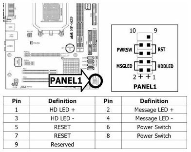
(Image via fixya.com)
Your Motherboard’s JFP1 Array
In order to allow you to switch on and reset your PC, as well as display an LED to indicate your PC is running and another to indicate hard disk activity, the JFP1 jumper must be correctly connected to your PC case.
As you might have noticed, JFP1 is an abbreviation, standing for “Jumper Front Panel 1” – if your motherboard has a JFP2 array of pins, this will be used for connecting audio, USB and perhaps eSATA case connectors to your motherboard.
If you don’t have a motherboard manual and cannot find one online (you can search the name of the motherboard as printed across it) you will generally find the JFP1 array in the lower right corner of the mainboard. You should also have a selection of connectors ready to plug in to the motherboard.
Connecting the JFP1 Array from Motherboard to Case
The connectors you have should allow you to connect the reset switch, power switch, case speaker, power LED and hard disk activity LED to your motherboard – the connectors will be labeled appropriately. Similarly once you have located the JFP1 array you should notice some annotation, indicating which pins are for which case connector.
It is then simply a matter of connecting as required. Note that the size of the connectors can cause them to be difficult to grab hold of, so you might employ something to position them accurately like a pair of plastic tweezers, for instance. Once each connector is correctly seated, you will then be ready to test the case switches and lights.